Intelligent Network Fabric (INF)#
The Intelligent Network Fabric is the network software stack from Evolving Networks. This is the public documentation for the INF and related technologies.
Network hypervisor with network RAID#
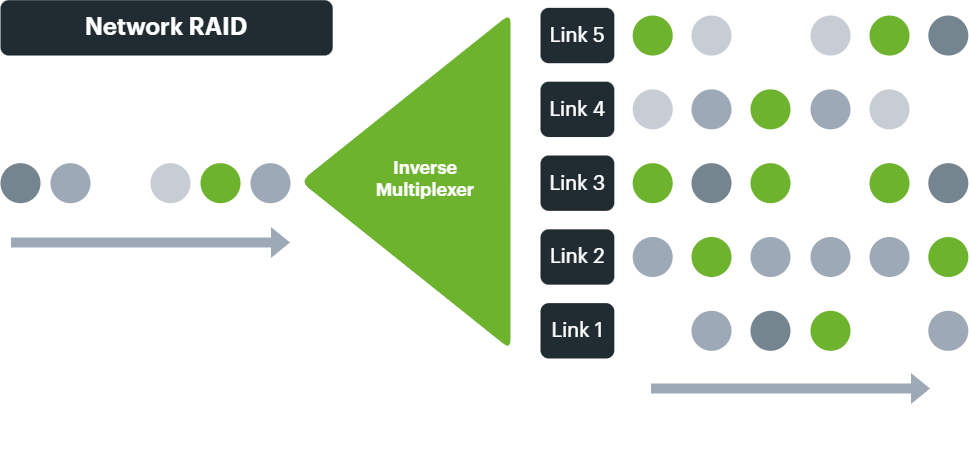
The easiest way of thinking about the Intelligent Network Fabric is as a network hypervisor with the network equivalent of RAID.
Just as creating multiple virtual machines on one or more physical nodes abstracts the software server instances from the server hardware, so the INF is used to create complex and varied WANs and internet connections transcendent to the circuits, modems and routers they are built on.
And with inverse multiplexing technology at the network packet level comes the ability to create redundant and resilient arrays of circuits, aggregating upload and download bandwidth into single logical data flows, and enabling a massive increase in network uptime.
Thus, internet, routed and Ethernet networks can be created with multiple sites and locations, just like having your own virtual smart Ethernet switch at your command.
Rethinking the OSI model#
The layered model of OSI can be helpful for traditional networking, although many mature network products and protocols such as MPLS and TCP/IP don't sit at any one layer.
With a new era in capability and virtualisation such that has been brought about by SDN and SD-WAN, a new model is needed.
Importantly, one must grapple with the concept that the physical will almost never match the virtual, and that traffic traditionally flowing on a lower layer may in fact flow above higher layers than the OSI model will strictly allow.
Abstraction, overlay and underlay#
If the physical individual circuits and datacentres form the network underlay components, and the network hypervisor provides a network fabric on top to them, then the networks created on top (that need bear no resemblance to the physical components) are abstracted meta or hyper networks.
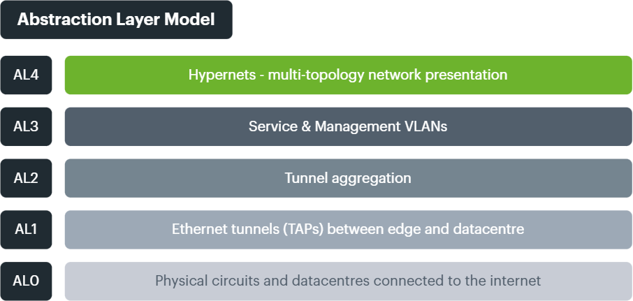
To help label and understand the processes involved, the INF conceptualises multiple Abstraction Layers, just like the legacy OSI model, but decoupled from its rigidity and designed for both complexity and flexbility (what we informally call "comflexity").
AL0: physical circuits and datacentres#
While traditionally the phsyical networking would be classed as Layer 1, abstracting adds additional layers. We define the component circuits of any connection as AL0, and call them "Links". Every Connection has at least one Link, and normally multiple Links for resilience, bandwidth and flexibility.
While able to utilise standard DIA (Direct Internet Access), private (RFC1918) and Layer 2 Ethernet for Links, typically DIA is preferred for building any Connection.
AL1: Ethernet tunneling as the new foundation#
In order to create abstracted Connections on top of multiple Links, and utilising all their bandwidth, first they have to be encapsulated and tunneled.
Using TAP, virtual Ethernet network devices are created using a choice of tunnel software (e.g. OpenVPN, GRE, FastD).
These tunnels, which we then refer to as TAPs, work with Ethernet frames, and allow them to traverse already routed (e.g. internet) Links.
By default, multiple TAPs are created for each Link, allowing network edge hardware (CPE such as the EVX, or virtual VNF instances) to create the AL1 layer to multiple NFRs (Network Fabric Routers) for resilience purposes (datacentre failure).
Encryption may be performed here or at AL3.
AL2: tunnel aggregation#
Operating in a similar conceptual manner to legacy LAG, but with the TAP Ethernet tunnels as their ports, AL2 is comprised of Tunnel Aggregation Groups (TAGs).
These logical constructs provide bandwidth aggregation capabilities similar to the Linux bonding driver and Libteam but with important additions such as improved packet management algorithms like Weighted Round Robin (WRR) to allow for the use of differing bandwidth circuits.
TAGs become virtual interfaces on EVXs and NFRs, and are used to logically collect Links together.
Connections will almost always have multiple Tunnel Aggregation Groups, fulfiling datacentre redundancy, hardware redundancy or Link redundancy (including traditional "failover" scenarios such as active/passive Links or collections of Links).
Once these multiple aggregated paths have been established, the service and management networks are then created, which form the foundation of the customer presented networks (hypernets).
AL3: Service & Management VLANs#
TAGs are logically split into Service VLANs - those that carry customer traffic, and Management VLANs - those that allow access to monitor, configure and manage the Connection.
Multiple service VLANs can be created, dependent on the number of network segments that are required at AL4.
Encryption may be performed here or at AL1.
AL4: multi-topology network presentation#
AL4 is conceptually where the hyper/meta-networks are created for each, or across all, endpoint sites and datacentre locations.
These virtual WANs are comprised of Hubs and Connections.
Hubs have Roles, such as Transit, Application, Security, Storage and can also have a Redundancy Level (where one Hub is primary and another is secondary)
Connections are edge sites connected with the INF to multiple Hubs, to allow access to services (internet access, cloud access, applications etc).
The network presentation layer is where the overall transcendent network design is realised.
- Raw Layer 2 across all sites?
- Public internet through a central firewall cluster?
- Private site to site routing with multiple VLANs per site?
- All of the above?
Here complex topologies can be created which bear no resemblance to the underlying AL0 circuits which may only individually connect to the internet.
AL4 network designs need not be homogenous across all sites.
AL4 is also where Access Control Lists (ACL) reside to make security decisions between network segments and where QoS is performed to prioritise applications and protocols by packet.

