Tunnel Aggregation Groups#
Tunnel Aggregation Groups (TAGs) are used to collect and contain the TAPs created on Links to aggregate and vector traffic dependant on the redundancy scenario.
They are one of the most powerful building blocks we have in creating hypernets, allowing us to virtualise connectivity in more than one way, enabling bandwidth aggregation, path preference and redundancy options.
TAGs contain a minimum of one TAP in order to be able to pass data and be useful.
Their default, like TAPs, is to operate at Layer 2. As soon as IPs are assigned, however, they operate like any other Layer 3 interface.
Basic configuration for standard aggregation#
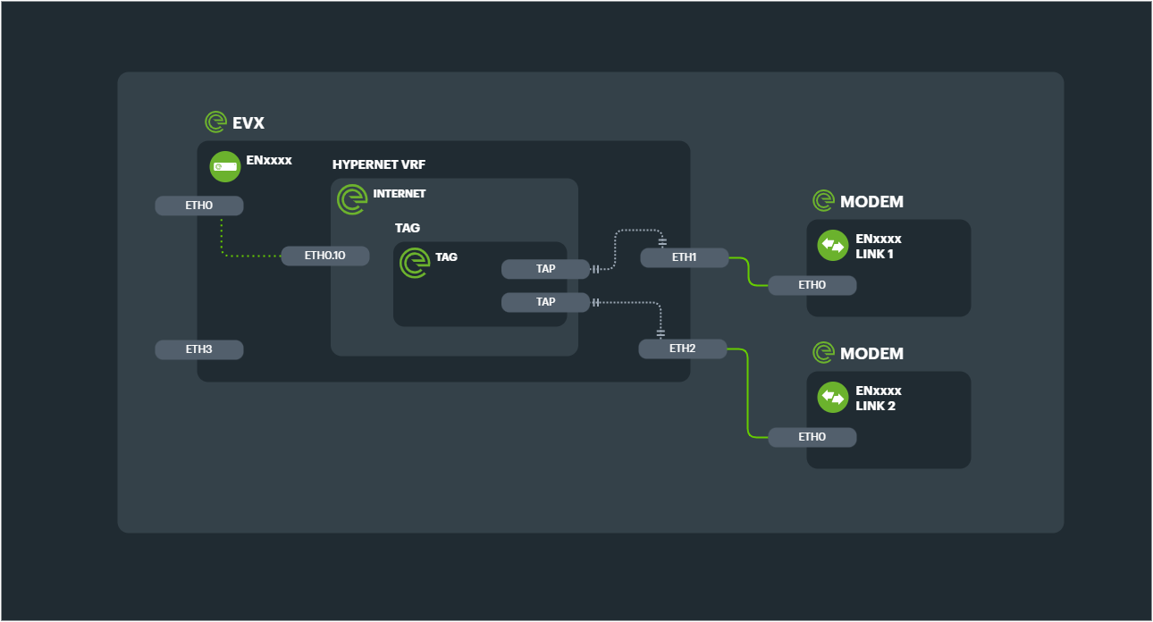
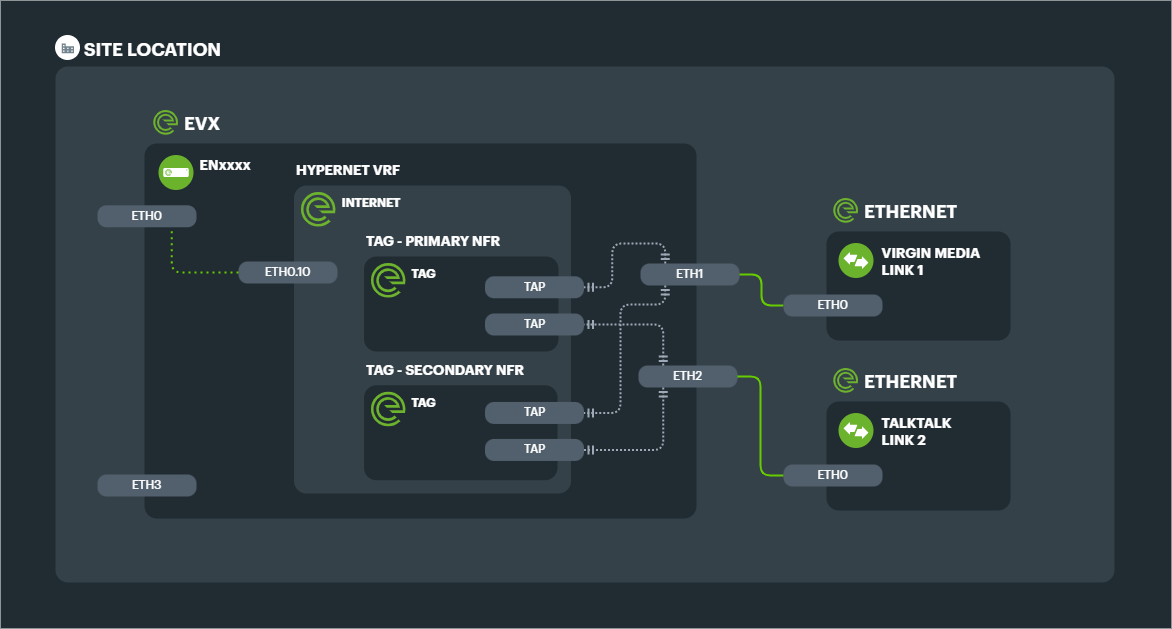
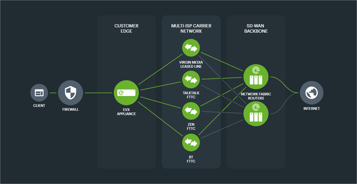
The simplest configuration for a Connection is a Primary TAG consisting of TAPs tunneled to a Primary NFR, and a Secondary TAG consisting of TAPs tunneled to a Secondary NFR.
This base level of Connection would aggregate the bandwith of the TAPs, and provide datacentre level redundancy.
Example
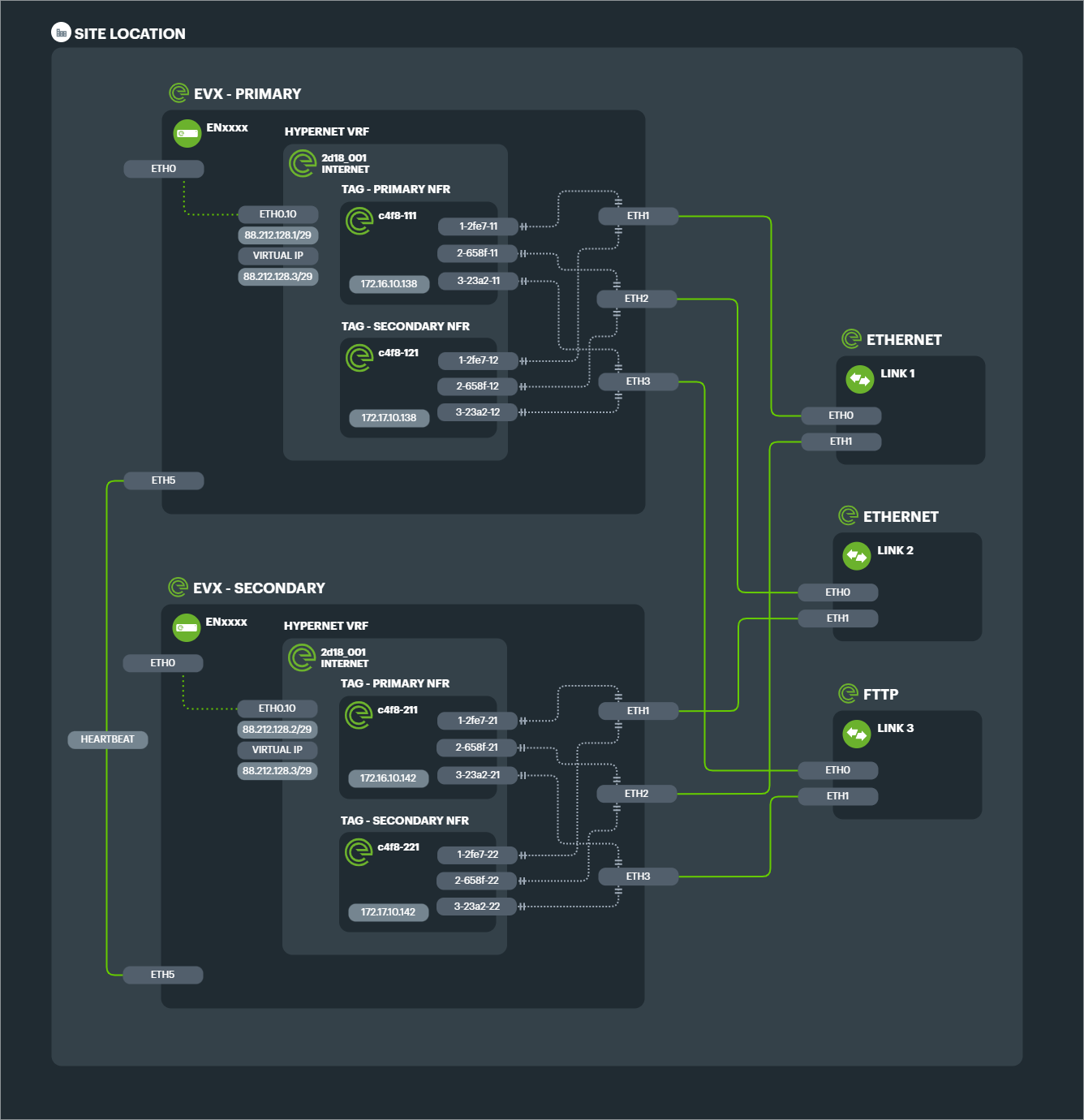
2x 1Gbps Ethernet lines aggregated to a single 2Gbps Connection, with a single EVX edge appliance and connected to 2x NFRs (for datacentre redundancy) would consist of 2x TAGs and 4x TAPs.
The configuration design below shows each TAG with its respective Ethernet tunnels (TAPS) connected to each of the 2 Links.
Failover scenarios#
While the TAGs provide in built fault tolerance by only requiring one working TAP at any given moment, more traditional failover scenarios such as active/passive can be configured and extended.
Legacy active/passive#
Legacy failover technology will use a primary circuit, and then if that circuit fails, a secondary circuit can be used instead.
This can be automated so that after detecting a failure (in usually seconds or minutes) the secondary circuit is switched to without manual intervention.
Or in a manual configuration, routers would need reconfiguring to use the secondary circuit, and would perhaps even need to be physically recabled.
Typically the IP address would have to change when switching to an alternative circuit in this way.
Much faster convergence times#
By using aggressive tunnel monitoring, convergence times for TAP failure are brought down to sub-second intervals, meaning seamless adaptation to component failure.
By using the INF and TAGs to perform basic active/passive failover connections, Secondary Links are monitored continuously, along with the Primary Link, so that the state of both is always known.
Convergence is configurable, but by default 300ms, providing an immediate improvement to traditional failover times.
Multiple secondary circuits#
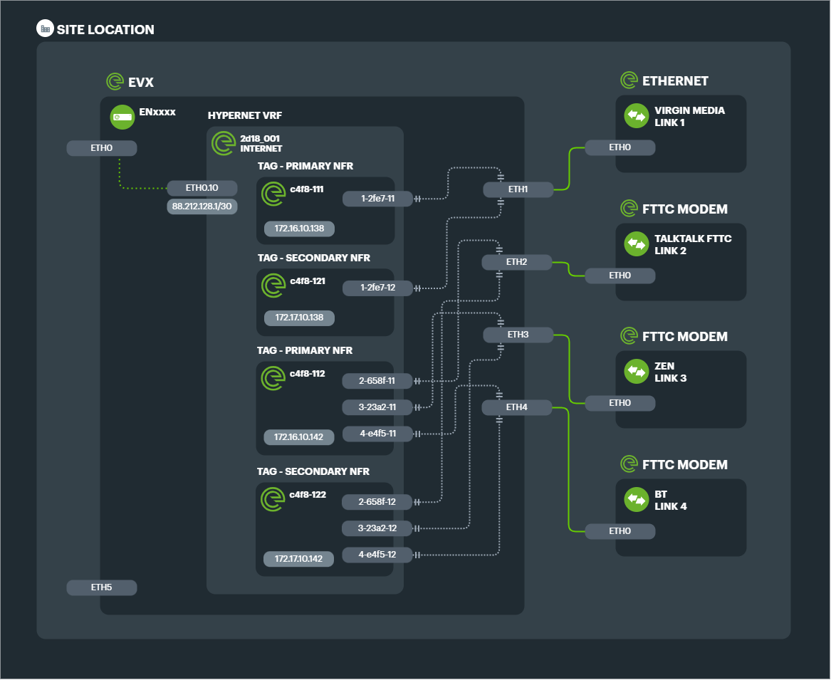
Along with allowing multiple primary circuits to aggregate bandwidth, There is no limit of 1 Secondary passive Link, as in legacy failover. This means Secondary TAGs can have flexible bandwidths and Primary and Secondary TAGs can have a mix of circuit technology to achieve the desired balance of risk versus bandwidth.
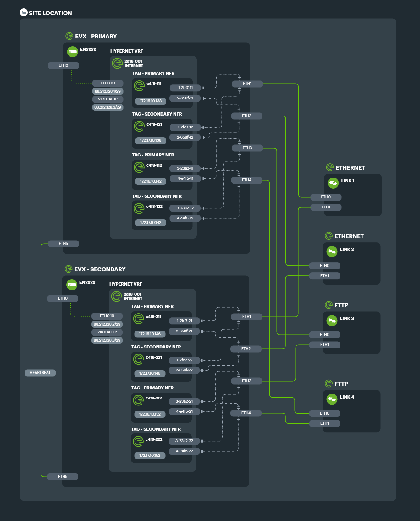
Example: 1x 1000mbps Ethernet leased line as Primary, with 3x 80/20mbps FTTC broadband lines as Secondary.
The configuration design for the above solution shows the 4x TAGs and 8x TAPs required in link preference groups. Note that both link preference TAGs connect to both Primary and Secondary NFRs for ultimate redundancy.
Multiple link preference levels#
This technique drastically increases the options for organisations wishing to improve resilience without matching circuit for circuit.
Further levels of link preference can also be achieved, so that more than one fallback option exists from the primary connectivity.
Example: 2x 1Gbps Ethernet leased lines as Primary, with 2x 100mbps Ethernet leased lines as Secondary and 4x 80/20 FTTC broadband as Tertiary.
IP affinity#
Because the hypernetwork is where the IP addressing of the Connection resides, the act of changing which circuit is in use has no change of IP.
The subnet in use, whether private or public, is abstracted away from the physical level (Abstraction Level 0), so that it need not be dependent on physical changes.
Regardless of NFR preference, link group preference or phsyical device, the IP address schema for the overall connection stays the same.
Complex configurations#
High Availability (HA) EVXs#
With an HA cluster of edge appliances, each will have a TAG and associated TAPs configured to connect to Primary and Secondary NFRs.
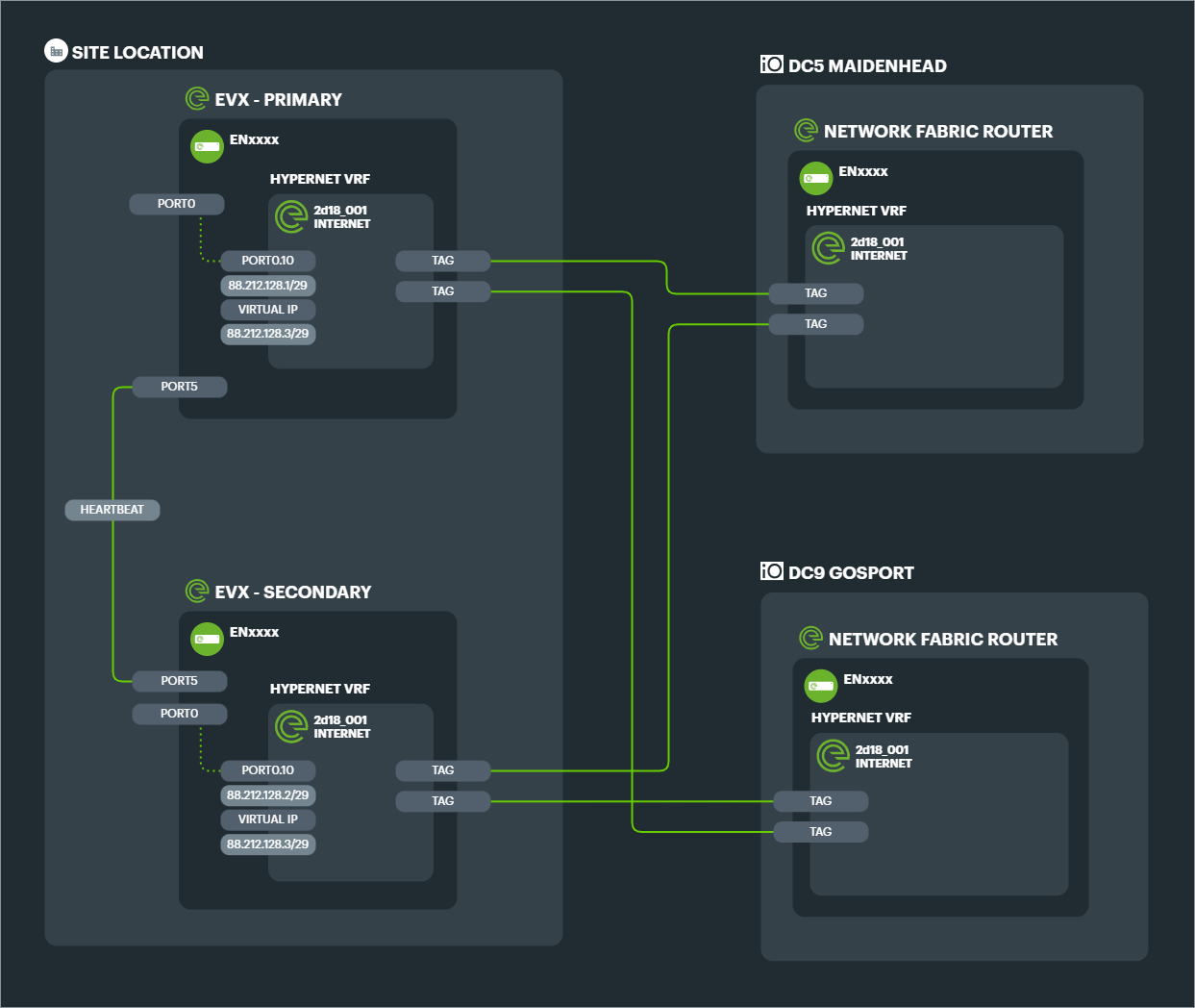
In a standard configuration of purely aggregated Links in a single Connection, this means a minimum of 4 TAGs for the entire Connection, and TAPs equalling 4x the number of component Links.
Example: Connection consisting of 3x FTTC Links with dual EVXs (HA) connecting to dual NFRs (geographically diverse datacentres).
The resultant configuration has 4x TAGs and 12 TAPs.
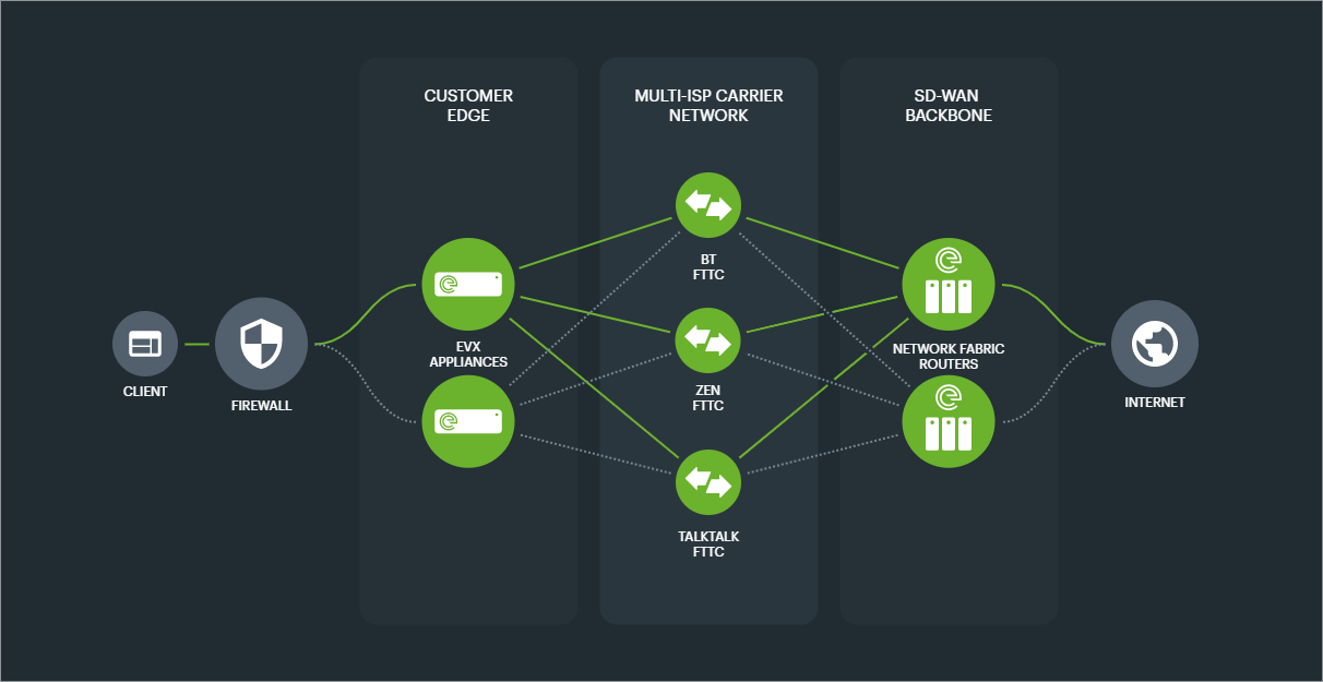
Combining HA and failover TAGs#
The number of configured TAGs and therefore potential logical paths for data to vector increases when employing multiple tactics to achieve Connection uptime.
Example: 2x 1Gbps Ethernet leased lines aggregated as Primary, with 2x 1000/115 FTTP aggregated as Secondary, with dual HA EVXs and dual NFRs. This single Connection would entail 8x TAGs and 16x TAPs even though there is only a total of 4x Links.
Note that in the above scenario, even though there are technically 16 different permutations of physical paths that can be taken by any data packet, the connection would maintain exactly the same hypernet configuration - potentially a single public IP range to the internet. No matter the change in path, this IP range would persist.
Service & Management VLANs#
A default configuration consists of creating subinterfaces on TAGs, so that management access is separated from customer hypernets.
The use of a separate management VLAN on the TAG means that there is technically a management hypernet, which can have an address schema and access rules independent of the customer hypernets, which exist on their own VLAN or VLANs as necessary.
In practice VRFs are also established for each Link.
Note: Service VLANs on the Tunnel Aggregation Group exist at Abstraction Level 3 below the customer hypernets at Abstraction Level 4
Management VLAN#
A subinterface of .10 is created on every TAG, with a private IP assigned. This network connects the EVX to the NFR and allows for the routing of a public internet subnet to every EVX for management purposes.
Regardless of the customer configuration (e.g. raw Layer 2 connectivity), there will therefore always be access for monitoring, telemetry and management.
Service VLAN(s)#
By default, 1 subinterface of .20 is created on every TAG which acts as the path for the customer networks (hypernet).
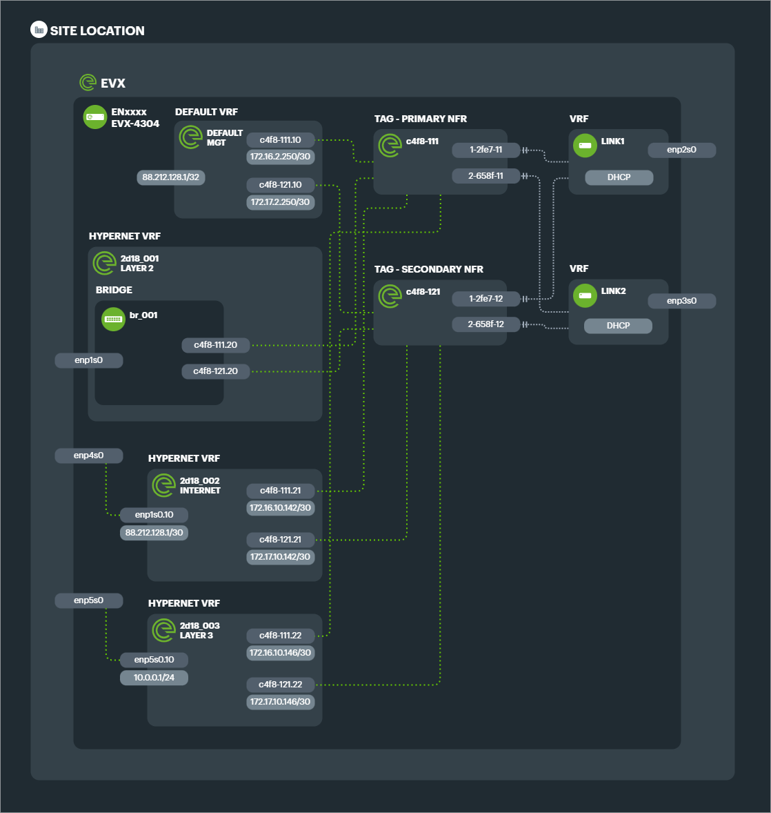
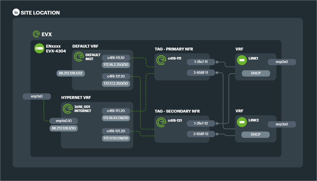
Example: 2 Link aggregated connection with Management VRF and Hypernet VRF delivering simple internet breakout on a single IP range.
If a hypernet segment is to be Layer 2, then this subinterface is bridged with the physical LAN port on the EVX, or with other TAGs on the NFR.
If the network segment is to be Layer 3, then private IPs are established on the subinterface ready for routing either a public subnet to the EVX or private subnets in the organisations schema for that Connection at that site.
Multiple Service VLANs can be created as subinterfaces of the Tunnel Aggregation Group depending on the number of different network segments required in the hypernet.
Example: Site A requires a Connection that has 1 phsyical port connected to the LAN switch for trunking VLANs to Site B, 1 phsyical port connected to a local firewall which needs a public IP range, and 1 physical port with a private LAN range that routes to Site C. 3 Service VLANs would be created as subinterfaces of the TAGs.
Then depending on the segmentation required, up to 3 Hypernet VRFs would be created to match those 3 distinct topologies. Each is connected to the TAG VLANs for that network segment.